
3D Inspection System Examins Connector Pin Height
Advance could save connector manufacturers money and reduce recalls for automotive, aerospace, and other industries
-
 Before connectors enter the 3D vision system for board-side scanning, they are inspected to verify that the correct part is present and that it’s in the proper orientation.
The global market for the Connectors industry is estimated to reach USD 80.3 billion by 2022, driven by the growing demand for reliable, fail-safe electronics in a wide range of industries, including automotive, aerospace, and defense/ military. Faulty connectors buried deep within a major electronic subsystem in a car or an airplane can have catastrophic results. Failures in inspection systems can lead to loss of life and costly, massive product recalls. A new 3D inspection system could be the solution.
Save lives, reduce costs
G2 Technologies, a test and measurement company with clients like Honda, 3M, BE Aerospace and NASCAR, has developed a first-of-its-kind, customizable, automated 3D inspection system to catch flaws that previous inspection systems would miss. According to Craig Borsack, P.E., president of G2 and an industry expert, “Inspection historically has been limited to 2D and the human eye. Not anymore. With state-of-the-art 3D systems, companies can catch their mistakes before it’s too late. That’s important when lives and millions of dollars are at stake.”
Borsack said if a tier-1 automotive supplier, for example, integrates a bad connector into an Engine Control Unit (ECU), and that ECU gets sold to an automotive manufacturer, is installed in vehicles and results in a recall, much of the associated cost will likely be charged back to the connector manufacturer.
In order to minimize the risk of faulty connectors making it into the supply chain, engineers at G2 Technologies have developed an automated connector inspection system. The system, built on the PXI platform from National Instruments combines a machine-vision based non-contact 3D inspection system, a cleaning station, electrical test and engraving stations.
Too short?
“With contact inspection and the human eye alone, inspectors could see bent pins and missing pins all day long, but could easily miss a faulty connector with a pin that was just too short,” said Borsack. “Now with this customizable application, they are able to use noncontact inspection and spot these faulty connectors that were previously making it through the process. This is a huge improvement and one that could save connector manufacturers millions of dollars or more each year.”
Short takt time
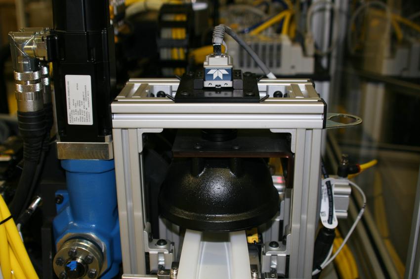
Borsack said that his company was able to achieve a 3.5 second takt time on each part. And G2 was able to develop a system that has the flexibility to inspect various connectors with pin counts ranging from four to 32, and deliver one-cycle rolling changeovers between parts. The inspection system is installed after stitching, a process that accumulates contact pins and inserts them into molded connector housings. Stitched connectors enter on an input conveyor and pass under a Genie Nano M1920 GigE Vision camera from Teledyne DALSA. An image of the connector is acquired with illumination provided by a DL 194 diffuse dome light from Advanced Illumination. The image is then analyzed to verify that the correct part is present and that it’s in the proper orientation to proceed through the inspection process. If the part is not correct or is improperly oriented, the system diverts it into a reject bin.
Double-scanning
Parts deemed correct and that are properly aligned proceed to an orientation wheel that repositions the part board-side down, for the next station, which is board-side inspection. At this station, a scanCONTROL 2650-25 laser line profiler from Micro Epsilon scans the entire board side of the connector. After board-side inspection, connector-side inspection takes place. Due to cycle time requirements, and the need to scan the part from both directions, inspection of the mating side of the connector is performed at two stations by two additional laser line profilers. “Two scans are required due to shadowing effects created by the connector shell as the part is scanned from one side,” explains Borsack. “In order to get a complete 3D point cloud, the part must be scanned from both directions, then the images are combined to mask out the shadows.”
The system scans from both sides and creates a plane based on a pad on the bottom of the mate side connector. This plane will be used to measure true position and pin height of the contacts.
After visual inspection, the connector goes to a cleaning station, followed by electrical testing, and finally, each connector goes through an engraving station. Passing connectors receive a date code and proceed to packaging. Failing connectors receive a reject code identifying in which station it was rejected and are moved to a locked reject bin to ensure that they don’t get mixed with good parts. Borsack hopes connector manufacturers will consider exploring this for their companies. “It’s a small price to pay when you look at the potential savings it offers. Not only can this inspection system help protect a manufacturer from being sued for millions of dollars in damages in a recall situation,” Borsack said. “It could also absolutely save lives.”
Contact
G2 Technologies
1050 Classic Road
NC 27539 Apex
+1 919 589 9064
+1 919 589 9103