Automation of Hot Forming and Laser Cutting Processes
A lot has already been written about problems that generally arise in bin picking solutions and applications. This article, in contrast, will present a case study describing a bin picking system for the automation of hot forming and laser cutting processes developed by Photoneo for a specific customer. The custom features, specially developed for this client, have been transformed into generally available ones that are currently deployed by a wide audience of users.
Hot Forming and Laser Cutting System
In 2018, Photoneo accomplished one of the biggest installations of its bin picking systems. The whole project consisted of 11 bin picking cells, including 11 robots and 11 scanning devices. The systems are currently handling 18 types of objects. The entire deployment was delivered to one of the biggest automotive suppliers of metal components for car chassis, and Photoneo was asked to help automate its hot forming and laser cutting processes.
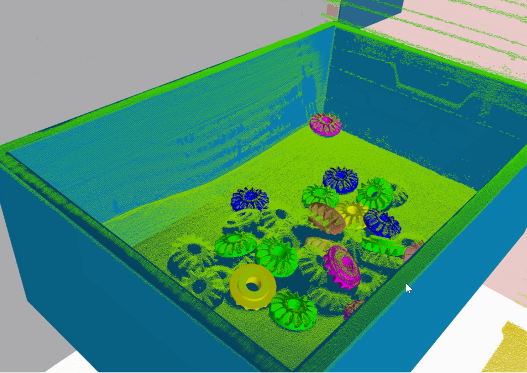
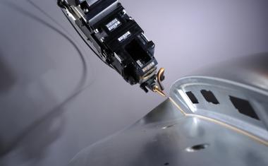
The procedure is as follows: After the hot forming process, raw parts are transferred to an input pallet of the bin picking system. The scanner scans the input pallet, localizes a part, and navigates the robot to a gripping position. The main goal of the entire manufacturing line is to precisely position the metal object into the laser cabin. The laser is then used to remove overpress as a side product of the hot forming. After this procedure, the robot takes the cut-off part out of the laser cabin and places the processed object into an output pallet. This process posed a number of challenges which the Photoneo team had to tackle.
The entire integration of the vision system was based on a regular release of Photoneo’s bin picking studio software. However, the process required several functionalities which had not been part of the release at that time. Since then, several updates have been released, the latest one being version 1.3.0 which contains all the above-mentioned required customizations. The new releases have been part of the company’s strategy to make all the custom features available to a wider audience of experienced users.
Additional Specialized Software Features
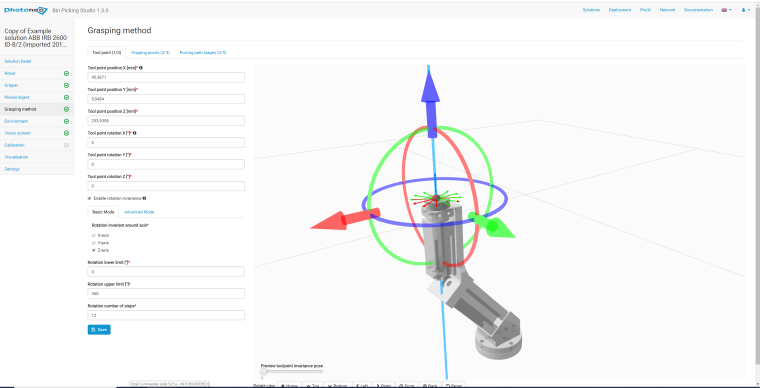
Among other features, the customizations included multiple vision systems and a so-called teaching gripping point option. The latter has been implemented as a result of difficulties related to the physical shape of the objects handled, which is rarely symmetrical. When combined with an imprecise stacking pattern, the possibilities of gripping poses are rather limited. This is why teaching of the gripping point is an extremely useful feature. The whole idea is based on utilizing the localization of the part firmly attached to the tool of the robotic manipulator. The system localizes the translation and rotation of the part and its relative position in the reference frame of the robot. The pose of the robot as well as the orientation of the tool point is then read from the robotic controller. This way, the gripping point on the object is recorded and stored for future use.
Multiple Vision Systems
Most of the production lines contain two input boxes and two output boxes to optimize the production effectiveness. As soon as the first input box is empty, the robot moves on to the second box and continues in operation. In the meantime, an operator replaces the first, empty input pallet with new raw material. This process requires a scanning device above each of the two input pallets. However, in order to optimize the overall costs of the entire system, only one Phoxi XL scanner is used, which is mounted on linear axes. Two positions have been taught, one for each input pallet. As soon as the first input pallet is processed, the robot commands the linear axes to move above the second input pallet. In order to make this feature available for the entire ecosystem of the bin picking studio users, the concept of vision systems was designed.
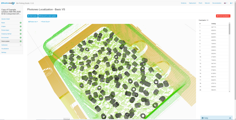
A vision system is defined by a particular scanner assigned to it and the calibration matrix transforming the scanner reference frame to the robot reference system. The vision system contains information about the localized object and the localization profile. One single scanner can be associated with several vision systems.
Overall System Accuracy
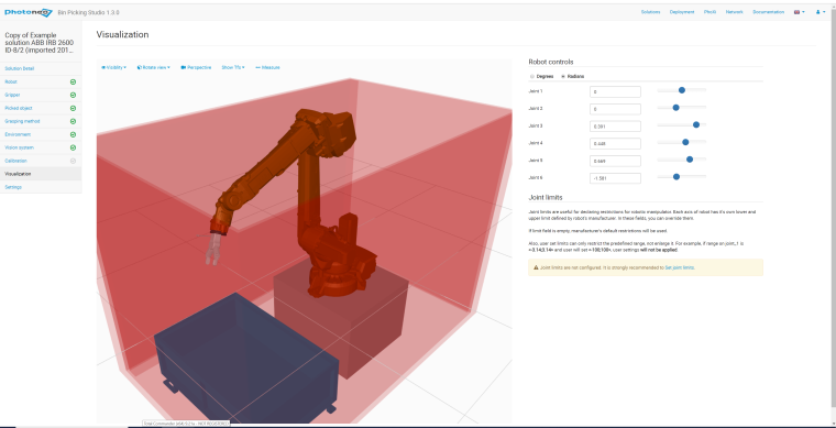
Another challenge which needed to be addressed was the accuracy of the entire system. The line consists of various components whereby each of these is manufactured with a certain precision. The robot used for handling the materials in this application was configured for a reach of 3.2 m and a load of 150 kg. While it provides excellent performance in terms of repeatability, the level of accuracy is more relevant in a bin-picking application. This is typically 8 to 15 mm.
In addition to the limited robot accuracy, a similar constraint was posed by Photoneo’s Phoxi 3D scanner XL. For this particular size and scanning volume, the point to point distance of the acquired point cloud is typically 2 mm and the calibration accuracy is 0,5 mm at the sweet spot.
The customer’s requirement was to localize an object using a scanner mounted 4 meters above the input pallet with a precision below 4 mm. Initially, this goal seemed mathematically impossible, since the inaccuracy of the robot, scanner, linear axes, localization algorithm and other systems and tools involved added up to a significantly higher number. To cope with this challenge, the company needed to develop a unique calibration method. For this, they used a special calibration object which was firmly attached to the tool. A number of various calibration poses were acquired in the volume where the future gripping point would be present. This method proved that a precise scanner-robot calibration process can compensate for a certain degree of inaccuracy of the individual components.
It might come as a surprise that seasonality can also contribute to inaccuracy. Because we are talking about light industry manufacturing here, the environment in the hall is very unstable. For an object made of steel 6 meters long, a change of the ambient temperature from 18 to 40 °C would cause a dilatation offset of 0.21 mm. These seasonal changes can be mitigated by a regular scanner-robot recalibration.
From Initial Challenges to New Features
The customer’s application posed many challenges which needed to be tackled to successfully perform the required processes. Besides the above-mentioned, there were many others such as objects that were not rigid, the security of the proposed solution, adoption of the present tool changer and advanced control options from the robotic controller, such as for example a solution switch, used to quickly change a particular solution in the control system. None of these was easy to tackle, however, in the end they all led to the improvement of already existing and development of completely new features in Photoneo’s products and solutions, which are now available to all users.
Company
Photoneo s.r.o.Plynárenská 6
82109 Bratislava
Slovakia

most read
Automatic Defect Detection in Laser Welding and Brazing with AI
Process Monitoring in Automotive Production.

“New technologies always start in R&D”
Kolja Haberland, CTO at Laytec, talks about the early years of the company and explains how they managed to grow from a three-person operation to a globally active medium-sized enterprise.
The Rise of Photonic and Neuromorphic Computing: A New Era for AI Hardware
Computer Architectures for future data processing
Active Alignment in Assembly and Connection Technology
Reliable manufacturing processes are essential for the assembly and connection technology of photonics systems. Common coupling methods of Active Alignment during assembly are described here.
It Does Not Always Have to Be a Humanoid Robot
Mythomorphic design adds a distinct perspective to social robotics. Inspired by myths and fantasy rather than humans or animals, the article classifies examples and examines related opportunities and risks.