LED Lighting in Inline Testing of Solar Cells
Automatic Cell Distance Measurement
The Photovoltaics (PV) industry is continuously working on improving the efficiency and performance of solar modules. The goal is to further increase the power per area and reduce the manufacturing costs.
The power of a solar module is expressed in watt-peak. This is the power output when the solar irradiation is 1,000 W/m2. A solar irradiation of 1,000 W/m² is achieved, for example, on a sunny day in midsummer. Because solar modules cannot be made arbitrarily large, manufacturers strive to maximize power per area. This is achieved, among other things, by using highly efficient solar cells and making the best use of the area when placing cells and electrical connections in the module. The position and spacing of cells and their connectors are precisely specified for production.
Cell Positioning
The positioning of the cells in the production line takes place in the stringer. In the stringer, the cells are connected with electrically conductive connectors, the ribbons, with gaps to each other of 1–5 mm. In the next production step, these “strings” are placed side by side on the front glass laid out with EVA film and are further electrically connected at the end or in the middle of the cell array. This connection is called the cross-connection. In the next step, another layer of EVA film and the backside film or glass is placed.
Before everything is laminated, i. e. before all layers are fused into an inseparable laminate, with the help of pressure and heat, it is important to check the position of the cells and the interconnection, as well as the perfect condition of the individual cells. After lamination, position corrections or replacement of broken cells are no longer possible. Since defective cells or faults in the cross-connection directly lead to power loss of the entire solar module, it is particularly important to find these before lamination.
This task is performed before placement of the 2nd EVA film and the backsheet/ back glass by the inspection system Solar Module EL-quickline from MBJ Solutions. In addition to an electroluminescence test (EL test), the inspection also offers the measurement of cell distances. While the EL test detects defects in the solar cells, the cell measurement measures the distances from cell to cell, cell to cross-connector and cell to glass. In addition, the edges of each solar cell are also inspected for the smallest cracks.
This is done fully automatically via a specially developed software which, in addition to measuring the cell distances, also offers AI-supported automatic defect detection for the EL test.
-
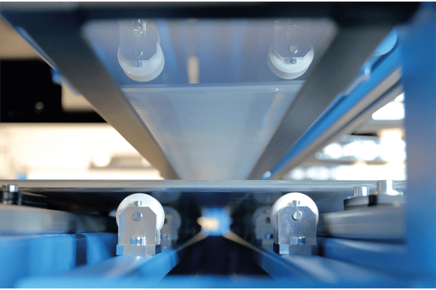 The MBJ Flexlight Back produces bright, timed flashes as the solar panel passes by. The cameras are located below the solar module. (Image: MBJ)
 -
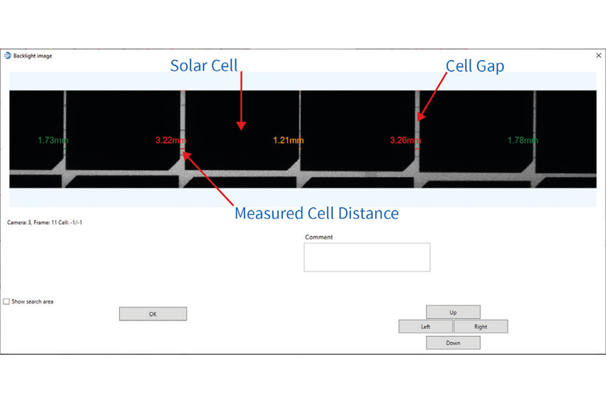 Cell gap measurements with automatic judgment: A solar module showing gap sizes larger than 3 mm will be color marked in the software and automatically forwarded to the repair station. (Image: MBJ Imaging)
 -
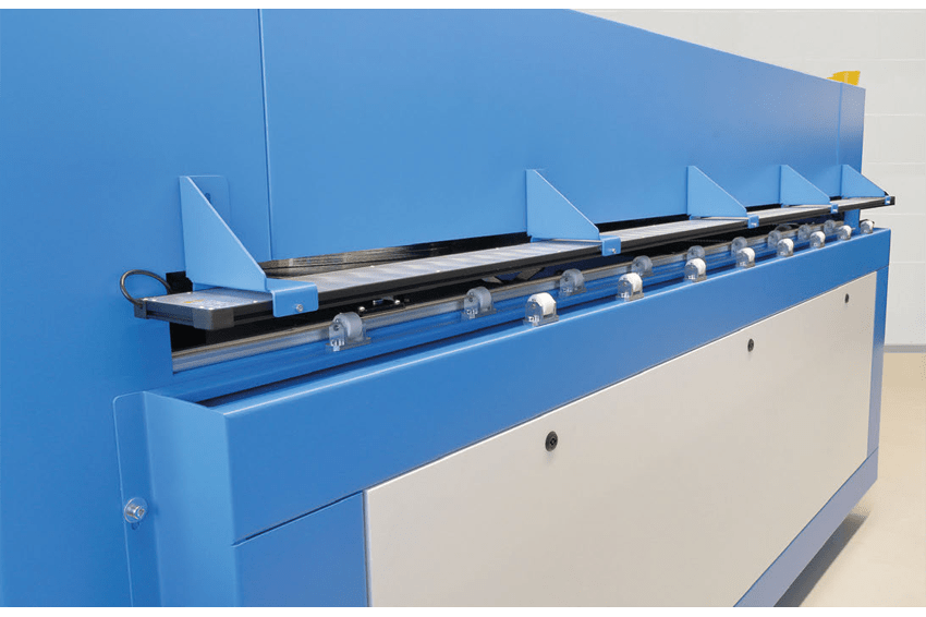 The 2.5 m long illumination from the MBJ Imaging Flex series mounted onto the Solar Module EL-quickline inspection system. The solar modules are measured in motion, during loading. Inside the machine, another inspection takes place: electroluminescence imaging. (Image: MBJ Imaging)
Cell Measurement
Since the module transport inside the machine obscures important areas of the module for cell measurement, the inspection is performed “between” the system and the upstream conveyor, while the module is being transported into the machine. The cell measurement works in transmitted light with diffuse illumination shining directly through the module into the cameras below. In the software, the cells then appear dark against a bright background.
In order to be able to measure the entire solar module area while it is moving, many partial images of the solar module are taken in rapid succession. The camera used is a Basler Dart camera with USB 3.0 interface and area sensor; the cameras’ field of view is 70 mm. The captured images are directly transferred to the software and evaluated. The number of cameras depends on the length of the solar module to be inspected.
Lighting Requirements
The lighting must provide bright homogeneous illumination over a length of 250 cm and a width of 7 cm. To ensure razor-sharp images during rapid movement, the system can be operated with a loading speed of up to 500 mm/s, the lighting must also provide a fast and precise flash frequency. Due to the expected short flash times, given by the speed, a lot of light is needed.
The LED Flexlight Series
The Flex series from MBJ Imaging offers the possibility to build a customized illumination adapted to this application. The standardized modular system allows a high degree of individualization and adaptation to the inspection task at very attractive prices. The Flex illuminations are available as top, back and bar lights, which can be individually selected in width and length. In addition, LED color and beam pattern can also be customized. These options are ideal to adapt them to the given inspection task.
For the inspection task “cell measurement” a diffuse MBJ Flexlight back with white LED’s (LED color white with 5000 K and CRI80) and an illuminated area of 250 cm length and 8 cm width was chosen. The illumination is controlled with LED controllers type CTR-51 also from MBJ Imaging.
The CTR-51 is designed for high frequency, high current flash applications. The flash energy is provided by an internal capacitor bank and the voltage regulation ensures a constant brightness intensity. The shortest feasible pulse length is 1 µs. The flash frequency is also sufficient for linescan applications and a flash current of up to 30 A is available.
Overcurrenting
The cell measurement works with a resolution of 200 µm per pixel at a maximum speed of 500 mm/s. This results in a flash time of 400 µs to get sharp images from the moving target and a duty cycle of one percent at a clock rate of 40 ms. To generate enough brightness for image evaluation in the images, the LEDs must be overcurrented 8 times.
LEDs can be overcurrented by a multiple given very short duty cycle without affecting the LED lifetime. How high this value is depends among other things on the cycle ratio. Under ideal conditions, an LED can be overcurrented up to 10 times for a very short period.
Due to the size of the lighting and the resulting number of LEDs, one CTR-51 is not sufficient to drive it. In total, more than 60 A are required to achieve the 8-time overcurrent. In order to have sufficient safety in current and also voltage, the LED strips of the lighting are divided into four separate strings. These are each supplied by a CTR-51. In total, four CTR-51 controllers are connected and triggered synchronized to have enough voltage reserve at 24 V voltage per controller.
Special Trigger
A trigger generator specially developed by MBJ ensures the correct timing: It sends the trigger for the camera to start grabbing as well as the slightly delayed trigger for the four CTR-51s. The delay is needed for the “rolling shutter” used by the camera. The camera images show, for example, solar cells in which the automatic cell measurement detected unacceptable deviations in the cell distances, or cell edge errors.
In a slightly modified application, solar modules are measured that are already covered with the back foil. The distances between the solar cells must be checked through this white opaque back foil. The back foil excludes illumination with white light, since this foil reflects almost 100 percent of the visible light. The back foil is also highly diffuse, making the diffuse Flexlight back not a good choice for the task.
A Flexlight Bar with a length of 250 cm, direct radiation and infrared LEDs is used for this task. The long-wave infrared rays can penetrate the back foil well and the direct radiation leads to a higher light intensity. A side advantage is that the infrared light cannot be seen by the human eye and thus an operator is not irritated by the flashes.
If defects or deviations of a defined size or number are found in the solar module, it is automatically ejected from the process and diverted to a repair station. There, the corresponding cells, or even entire strings, are replaced and the module is reintroduced into the manufacturing process. The insertion takes place before the inspection system so that the repaired module is also checked again.
“The close cooperation with the customer and the existing knowledge at MBJ Imaging from many years of development work in the field of LED lighting and machine vision has led here to a fast and high-quality implementation of the customer project” explains Andreas Bayer, Managing Director of MBJ Imaging.
Authors
Andreas Bayer
CEO
Svenja Petschelies
Technical Marketing